Build a complete OBD-II scanner without a car and without hardware
Category: Automotive firmware
This project runs scanner firmware and vehicle electronic control unit (ECU) firmware on a virtual test bench. The scanner runs on an nRF52840. The scanner uses an external MCP2515 controller for Controller Area Network (CAN) communication. The scanner uses an SSD1306 display. The radio telemetry has the form of Bluetooth Low Energy (BLE) data. An STM32F103 runs the vehicle ECU firmware.
The test verifies processor instructions and peripheral drivers. The test verifies On-Board Diagnostics II (OBD-II) messages and ISO-TP transport. The test verifies that the scanner decodes the values. The test verifies display writes and radio payload bytes.
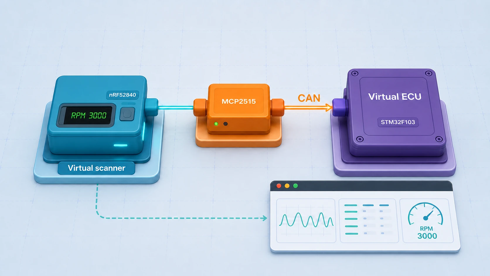
Run the complete virtual scanner
This is the two-MCU lab. The lab runs the nRF52840 scanner firmware against the STM32F103 vehicle ECU. The connection uses the modeled MCP2515 and the shared CAN bus. Watch the decoded vehicle data reach the OLED. Watch the decoded vehicle data reach the BLE telemetry. The lab does not use a car. The lab does not use a development board.
The required scanner result
The scanner must complete these operations:
- The scanner sends requests to the functional OBD-II address.
- The scanner receives replies from the physical ECU address.
- The scanner reconstructs the vehicle identification number (VIN).
- The scanner reads two diagnostic trouble codes (DTCs).
- The scanner clears the DTCs.
- The scanner updates the OLED display.
- The scanner transmits radio data that matches the vehicle data.
The native end-to-end gate produced this summary:
RPM 3000, speed 88, coolant 90, VIN LWOBD2SIM00000001,
DTC clear confirmed, CAN frames 21, BLE transmissions 4
The committed native end-to-end gate reads the exported firmware state. The native end-to-end gate inspects the CAN history. The native end-to-end gate sends a Mode 04 clear request. The native end-to-end gate checks the radio bytes.
The nRF52840 needs a CAN controller
The nRF52840 does not contain a CAN controller. The SPIM2 peripheral drives an MCP2515 instead.
The connections are:
- Chip select: P0.12.
- Interrupt: P0.11.
- SCK: P0.13.
- MOSI: P0.14.
- MISO: P0.15.
Firmware configures the MCP2515 transmit buffers and the receive buffers. Firmware configures the standard-ID masks, the filters, and the interrupts. The model connects the MCP2515 buffers to the shared virtual CAN bus.
The MCP2515 is only the CAN controller. A physical design also needs an automotive CAN transceiver between the controller and CAN-H/CAN-L.
The virtual bench
The system runs two Cortex-M firmware images:
- The nRF52840 scanner connects through SPIM2 to the MCP2515.
- The MCP2515 uses classical CAN at 500 kbit/s.
- The STM32F103 vehicle ECU connects through bxCAN to the same bus.
- The nRF52840 TWIM0 on P0.26/P0.27 connects to the SSD1306 at address
0x3c. - The nRF52840 RADIO provides captured nine-byte telemetry records.
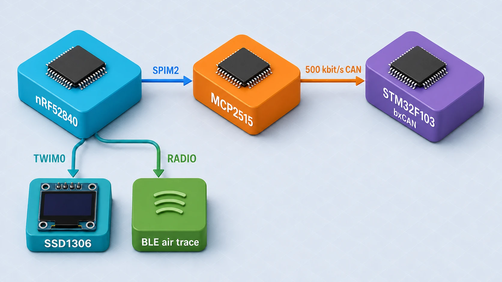
The lab source defines both machines and the shared environment. The scanner firmware is in the nRF52840 firmware crate.
Real OBD-II request and response frames
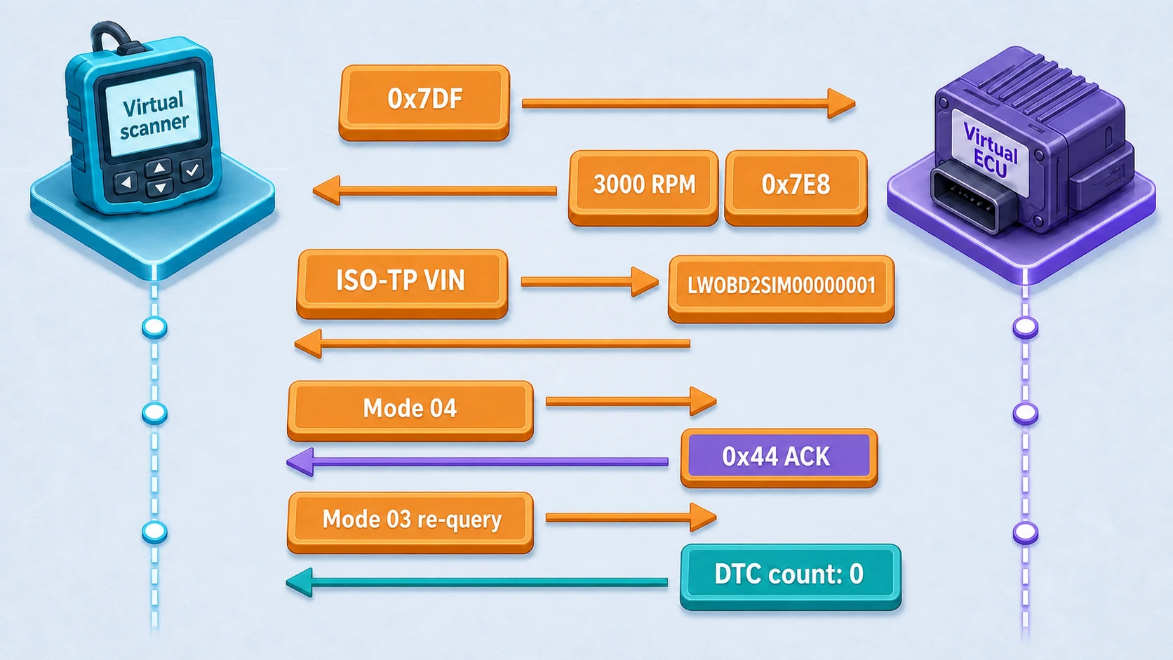
The scanner sends eight-byte functional requests on CAN ID 0x7DF. The ECU replies on 0x7E8.
Engine speed:
0x7DF  02 01 0C 00 00 00 00 00
0x7E8  04 41 0C 2E E0 00 00 00
Road speed:
0x7DF  02 01 0D 00 00 00 00 00
0x7E8  03 41 0D 58 00 00 00 00
Coolant temperature:
0x7DF  02 01 05 00 00 00 00 00
0x7E8  03 41 05 82 00 00 00 00
The ECU host test checks these exact bytes. The scanner decoder uses the same bytes.
Values, the VIN, and trouble codes
SAE J1979 defines the value formulas:
- RPM:
((A × 256) + B) / 4→((0x2E × 256) + 0xE0) / 4= 3000 RPM. - Speed:
A→0x58= 88 km/h. - Coolant:
A − 40→0x82 − 40= 90 °C.
The Mode 09 PID 02 VIN response is longer than one CAN frame. The ECU sends an ISO-TP first frame. The ECU waits for flow control on 0x7E0. The ECU then sends two consecutive frames. The scanner reconstructs the 17-character VIN LWOBD2SIM00000001.
Mode 03 initially returns DTCs P0133 and U0123. ECU host tests and scanner decoder unit tests check these identities. The native end-to-end gate checks that the scanner sees two DTCs. The native end-to-end gate then sends Mode 04. The native end-to-end gate receives the 0x44 positive response. The native end-to-end gate confirms that the next Mode 03 response contains no DTCs.
The OLED display
The nRF52840 writes to the SSD1306 through TWIM0. Firmware creates one scanner snapshot with RPM, speed, coolant temperature, DTC count, and status. The display path and the radio path use the same snapshot.
The native end-to-end gate checks the decoded scanner state. A separate browser WasmWorld test boots both ELF files. The browser WasmWorld test checks that the SSD1306 framebuffer is not blank. The browser WasmWorld test does not check exact pixels or text. This article does not include a runtime browser screenshot.
The radio payload
The radio payload contains nine bytes: version, status flags, little-endian RPM, speed, coolant temperature, DTC count, and a little-endian generation counter.
After the DTC clear, the fixed bytes are:
01 01 B8 0B 58 5A 00
B8 0B is 3000 in little-endian form. 58 is 88. 5A is 90. The last shown byte is a zero DTC count.
The native end-to-end gate observed four transmissions. The native end-to-end gate checked the packet bytes. This test validates raw nRF RADIO packets with a BLE-shaped application record. This test does not validate a complete BLE Generic Access Profile (GAP) stack for advertisements. This test does not validate physical radio qualification.
Faults and deterministic CI
Focused tests cover malformed responses. Focused tests cover wrong CAN IDs and wrong PIDs. Focused tests cover negative replies and truncated payloads. Focused tests cover unsupported requests. Focused tests cover ISO-TP flow control and ISO-TP timing. Focused tests cover stale scanner values.
The native end-to-end gate checks both ELF files and the CAN history. The native end-to-end gate checks the exported scanner state and the radio packets. The native end-to-end gate checks the two-to-zero DTC clear sequence. The browser WasmWorld test checks shared CAN traffic. The browser WasmWorld test checks a nonblank OLED framebuffer. The browser WasmWorld test checks radio telemetry in the air trace.
Validated parts and physical needs
The test validates firmware modules. The test validates how the firmware handles OBD requests and OBD responses. The test validates the ISO-TP state machine and the MCP2515 register interactions. The test validates the format of the display data. The test validates how the firmware encodes the telemetry. You can use these parts on a board that uses the same pins and the same peripherals.
A physical product still needs:
- An automotive CAN transceiver, termination, and bias.
- Electrostatic-discharge protection.
- Surge protection and load-dump protection.
- The correct connector pinout.
- Protected 12 V input power.
- Reverse-polarity protection.
- Supply regulation.
- Ground connections.
- A decoupled supply.
- Sleep-current control and thermal tests.
- Oscillator-tolerance tests.
- CAN arbitration tests and error-confinement tests.
- Signal-integrity measurements.
- An antenna design and an enclosure design.
- RF coexistence tests and EMC tests.
- Regional radio certification and applicable vehicle compliance.
This virtual test provides protocol evidence and firmware evidence. This virtual test does not provide electrical, power, RF, environmental, or regulatory evidence.