Modbus RTU without a bus analyzer
Category: Engineering
A Modbus master with one sensor on the desk usually works. Problems show up with two or more devices on the bus: a reply gets cut off, a slave answers too early, two frames run together. Debugging that normally means an RS-485 adapter, a logic analyzer and reading hex. In LabWired you can now simulate the whole bus: the master, the MAX485 transceiver, the wire pair and two real sensors. It runs in the browser and in CI.
The setup
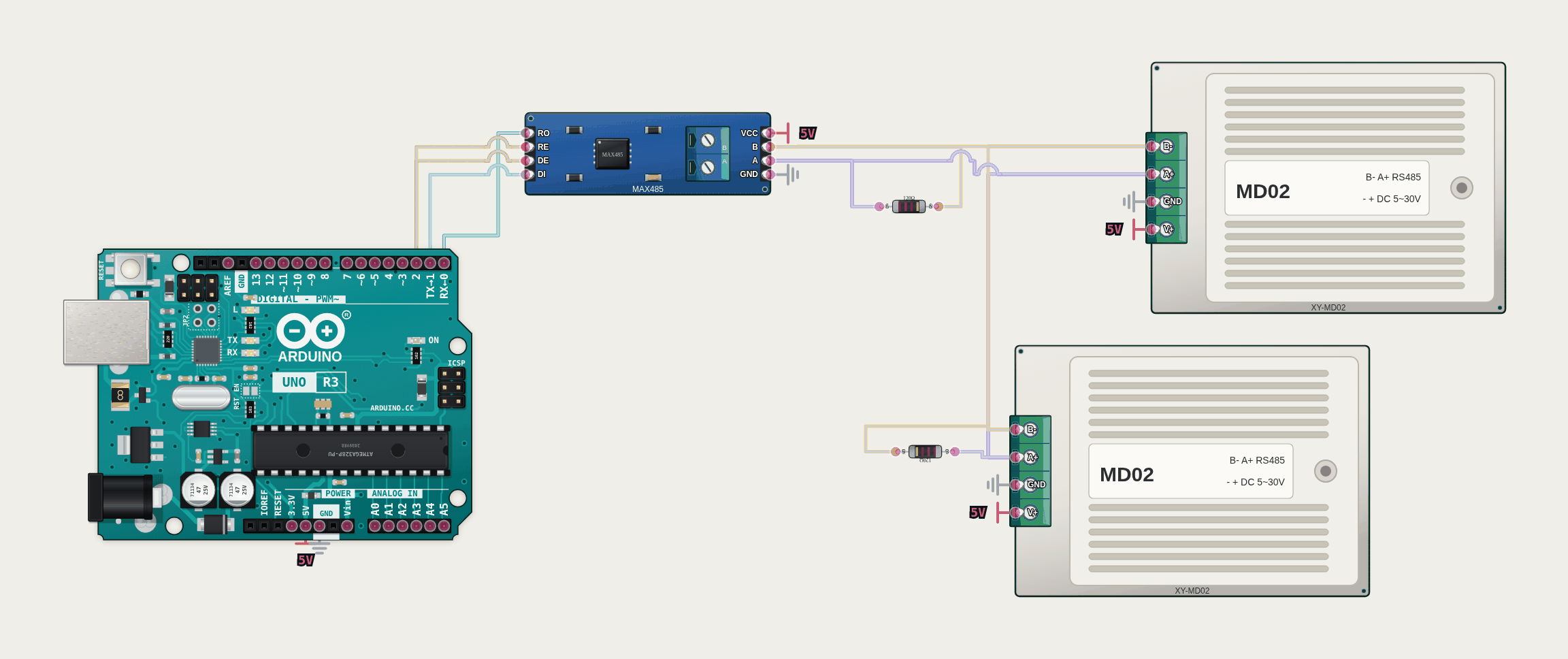
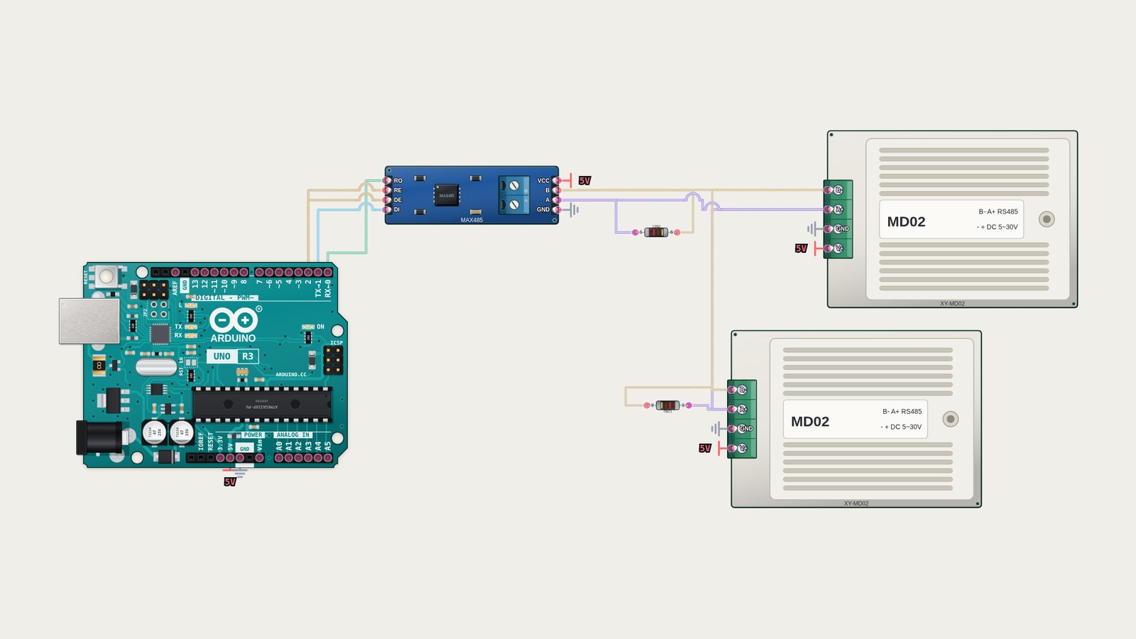
An Arduino Uno talks to a MAX485 on its UART. D2 drives DE and /RE together, the usual wiring. A and B go to two XY-MD02 sensors at addresses 1 and 2, with a 120 Ω resistor across the pair at each end. The XY-MD02 is an SHT20 temperature and humidity transmitter in a DIN-rail housing with a four-way screw terminal (B−, A+, GND, V+). The firmware is the ModbusMaster library (Apache-2.0) and a sketch of about sixty lines. Every half second it reads two input registers from each sensor, 0x0001 (temperature) and 0x0002 (humidity), and prints them.
The parts
MAX485. It passes bytes between the UART and the bus according to its pins. A byte from the Uno goes onto the wire only while DE is high. With DE high and /RE low, the Uno also receives its own frame back, as on real hardware. A reply from a slave reaches the Uno only while /RE is low. If a slave replies while DE is still high, or two slaves reply at once, the bytes collide and the run reports it.
XY-MD02. The sensor is described in a data file, using the register map from the manufacturer’s manual:
- Input registers 0x0001 (temperature, signed, 0.1 °C) and 0x0002 (humidity, 0.1 %RH).
- Holding registers 0x0101 (slave address), 0x0102 (baud rate), 0x0103 and 0x0104 (temperature and humidity correction, ±10.0).
- Function codes 03, 04, 06 and 10.
- CRC-16, and a frame ends after 3.5 character times of silence.
- Factory defaults: address 1, 9600 baud, 8N1.
Every example frame in the manual is a test. The manual lists no exception codes, so the sensor answers with the standard Modbus ones.
Try it
Open the example in the playground and press Run. Serial prints one line per sensor and poll:
poll 1 s1 T=21.5 H=48.0
poll 1 s2 T=19.0 H=55.5
poll 2 s1 reg 0x0200 -> 0x2
poll 2 s2 write correction -> 0x0
poll 3 s2 T=19.5 H=55.5
Select slave 1 and drag its Temperature slider; the next poll shows the new value. In poll 2 the sketch also reads a register that doesn’t exist, and the sensor answers exception 02. It then writes a +0.5 °C correction to slave 2 (holding register 0x0103). The change shows up in poll 3.
The frames
The MAX485 logs every frame on the pair. The playground shows the Serial output; the frame log is in the CLI and in CI:
| Time | From | Bytes on the pair | pymodbus decodes |
|---|---|---|---|
| 0.583 ms | master | 01 04 00 01 00 02 20 0B | slave 1, read 2 input registers from 0x0001 |
| 4.270 ms | slave 1 | 01 04 04 00 D7 01 E0 4B A4 | 215, 480 (21.5 °C, 48.0 %RH) |
| 13.295 ms | master | 02 04 00 01 00 02 20 38 | slave 2, same read |
| 16.982 ms | slave 2 | 02 04 04 00 BE 02 2B E9 DF | 190, 555 |
| 551.421 ms | master | 01 03 02 00 00 01 85 B2 | slave 1, read holding register 0x0200 |
| 555.109 ms | slave 1 | 01 83 02 C0 F1 | exception 02, illegal data address |
| 559.591 ms | master | 02 06 01 03 00 05 B8 06 | slave 2, write 5 to 0x0103 (temperature correction) |
| 563.279 ms | slave 2 | 02 06 01 03 00 05 B8 06 | write echoed back |
Times are simulated time. The 3.7 ms between a request and its reply is the 3.5-character silence at 9600 baud.
The frames are checked by the RTU framer from pymodbus, which is independent of our code. It decodes every frame, CRC included, and checks addresses and values. The same test also builds requests with pymodbus and sends them on the bus. Three kinds of request get no reply. They are a wrong CRC, a frame split by a gap longer than 3.5 characters, and an address that no device has.
The example firmware is a committed image, so the playground, the CLI and CI run the same bytes.
Limits
- Byte level only, no voltages. The termination resistors are in the diagram because a real bus needs them, but they don’t change what the simulation delivers.
- No parity, no second master. Slaves reply after 3.5 character times, not after a device-specific delay.
- The XY-MD02 is modelled as its manual describes it. The manual is unclear in places. It lists no exception codes. Its baud register table says codes 0 to 2, while its own example writes 9600. The part page documents what we chose. The manual’s text protocol (
READ,AUTO,BR:commands) is not modelled. - Another Modbus sensor is a new data file, not new code.