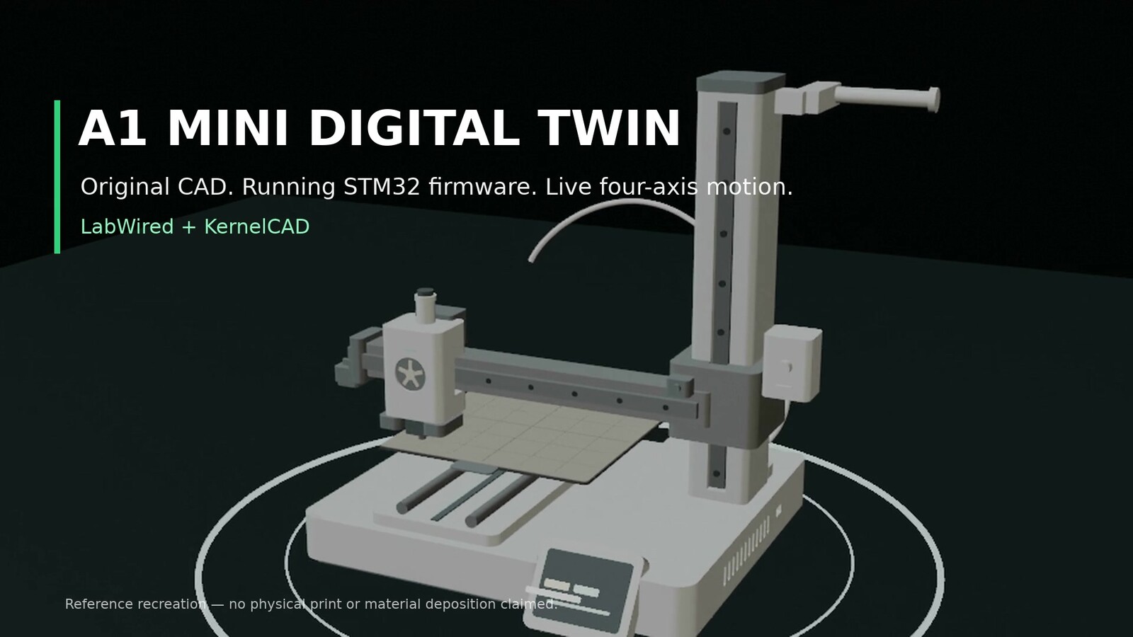
From schematic to motion: a 3D printer digital twin in LabWired
A firmware test can tell you whether a microcontroller executed its code. A machine test must go further: Did the axes move as commanded? Did the sensors change the machine’s behavior? Did the controller reach a safe state when something went wrong?
We built an independent desktop 3D printer reference to test these questions together. It combines a controller schematic and running STM32 firmware in LabWired with a constrained four-axis machine model in KernelCAD. An A1 mini-style printer provides the mechanical reference, but the CAD, electronics and firmware are original.
The project is public. You can run the saved simulation, inspect the controller and open the mechanical model.
One project, from firmware signals to machine motion
The LabWired schematic includes an STM32F411, four stepper-driver channels, three home switches, and hotend and bed temperature inputs. It also includes an OLED and controlled outputs for heaters, the fan and motor drivers.
The firmware runs against a declared verification scenario. The scenario supplies switch transitions and temperature inputs; the controller must respond to them. The motion model receives counted STEP edges and DIR states, so its movement follows firmware commands rather than a standalone animation.
Follow the firmware, not a scripted animation
The saved test first homes the three motion axes. It then commands a move to X30/Y30/Z1 mm, a 60 mm square and diagonal, a return move, and 6 mm of extruder travel. The test checks that the OLED framebuffer was painted and that controlled outputs return to their safe states.
The recorded sequence includes these markers:
HOME_X
HOME_Y
HOME_Z
ALL_HOMED
MOTION_START
PRINT_DONE
POSITION_STEPS 150 150 25 600
OUTPUTS_SAFE EN=1 HOT=0 BED=0 FAN=0
PRINT_DONE marks completion of the programmed motion sequence. It does not mean that a physical object was printed.
The connected KernelCAD model has 63 parts, including the moving bed, cantilever gantry, toolhead, filament path, display and auxiliary hardware. Its X, Y, Z and extruder joints follow the firmware’s counted motion commands.
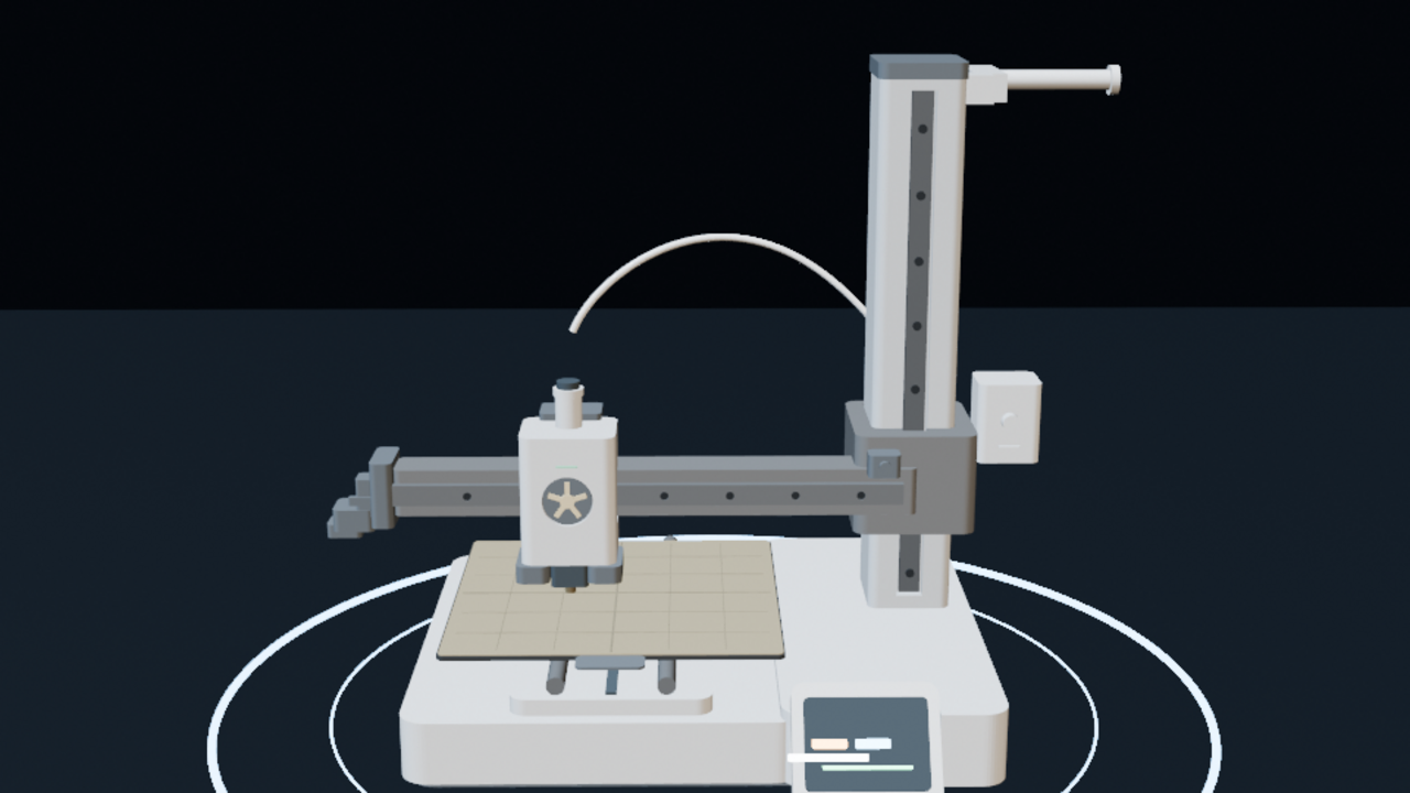
We checked 14 joint poses and 36 animation samples. Those samples showed no mate failures or detected collisions. They do not establish structural stiffness, drive torque or print quality.
Fault handling is part of the demonstration
A successful motion sequence is only half of the test. We also exercise faults and verify that the firmware responds.
| Test | Expected firmware response |
|---|---|
| Hotend overtemperature | Stop motion and return controlled outputs to a safe state |
| Invalid temperature input | Enter SENSOR_FAULT and shut outputs down |
| Emergency stop during motion | Disable drivers and prevent subsequent STEP edges |
| Missing home switch | Enter HOME_TIMEOUT rather than move indefinitely |
| Heater no-rise condition | Stop heating when the reported temperature fails to rise |
These tests verify controller logic under defined input conditions. They are not a substitute for physical thermal, electrical or product-safety testing.
A component-level controller PCB
The schematic and firmware are developed and tested in LabWired. As a separate hardware engineering reference, we also designed a six-layer, 140 × 105 mm controller PCB with 127 placed parts and 104 named nets.
The board is built around packaged components rather than plug-in development boards:
| Function | Component |
|---|---|
| Main controller | STM32F411CEU6 |
| X/Y/Z/E stepper drivers | 4 × TMC2209-LA |
| Power conversion | LM2596S-5.0 and AP2112K-3.3 |
| Hotend temperature interface | MAX31855KASA+T |
| MOSFET gate drivers | 2 × TC4427AEOA |
| Hotend, bed and fan outputs | 3 × IRLR2905Z |
The layout includes input protection, decoupling, motor and sensor connections, SWD, UART and OLED interfaces. The power outputs include gate resistors and pulldowns, with flyback protection for the fan.
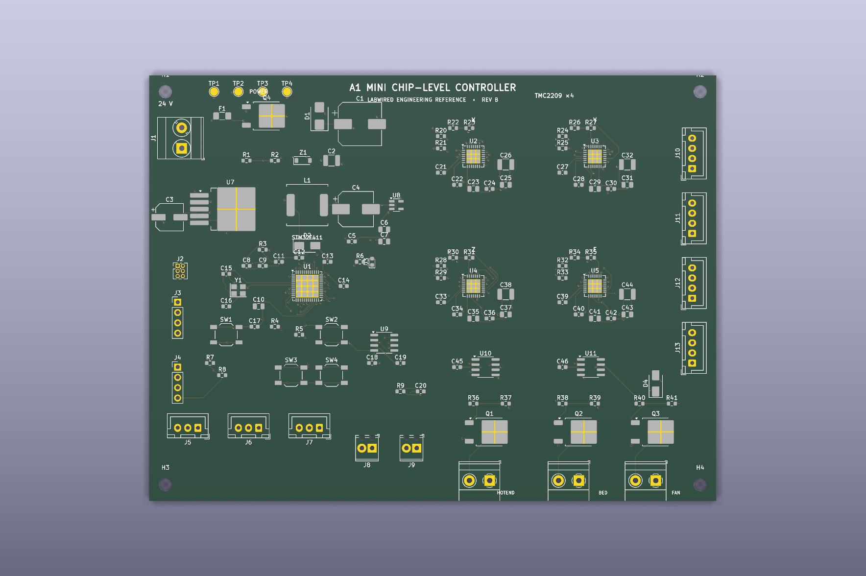
Geometry checks report zero violations. Four signal connections remain to be routed. Electrical margins, thermal behavior, EMC and manufacturing readiness still need validation before a physical board can be released.
What the digital twin proves
The public project demonstrates compiled controller firmware, sensor-driven homing, four-axis motion and OLED behavior. It also tests heater and fan control logic and fault responses. The linked CAD makes the commanded machine movement visible and inspectable.
It does not simulate filament deposition, melt flow, belt elasticity, motor stalls or print quality. The PCB is a design reference, not a qualified production board.
That distinction matters. A digital twin is useful when it shows which behaviors have been tested and which have not. Here, you can inspect the schematic, run the firmware and observe the corresponding machine motion before building hardware.
Independent engineering reference. “Bambu Lab” and “A1 mini” identify the commercial visual reference only. This project is not affiliated with or approved by Bambu Lab, and it does not use proprietary OEM firmware or CAD.