From a ChatGPT prompt to a running mixed-signal board
Category: Case Study
Can ChatGPT wire a circuit in the browser, write firmware, and show what happens when an analog input crosses a threshold? We used ChatGPT and the LabWired PCB MCP plugin to build a temperature alarm and run its firmware on a simulated Arduino Uno. We routed a two-layer board and reviewed its generated model. The missing Uno 3D asset renders as a solid placeholder that obscures the carrier board.
We imported four openly licensed boards made in Altium and KiCad. Each report lists modeled parts and unmodeled parts. It also says whether the design can become a runnable twin.
Open the runnable LabWired demo. The circuit and compiled firmware are saved in the share; press Run in the browser to execute it.
This case study follows two separate paths. First, we import existing designs and inspect coverage. Second, we build a small new circuit, execute its firmware, and route its PCB. The reference-board imports are not the source of the runnable temperature-alarm demo.
First check: what can the imported boards model?
The plugin imports native PCB files and returns a part-by-part coverage report. It does not invent pins for parts it cannot map. Here are four public reference-board imports:
| EDA and source | Mapped | Unmodeled | Ignored | Import result |
|---|---|---|---|---|
| Luxonis BW0253 Raspberry Pi HQ adapter, Altium (MIT license) | 9 | 8 | 32 | Design-only; no MCU mapped |
| ChipSelectCS ICM-42670-P breakout, Altium (MIT license) | 8 | 3 | 5 | Design-only; no MCU mapped |
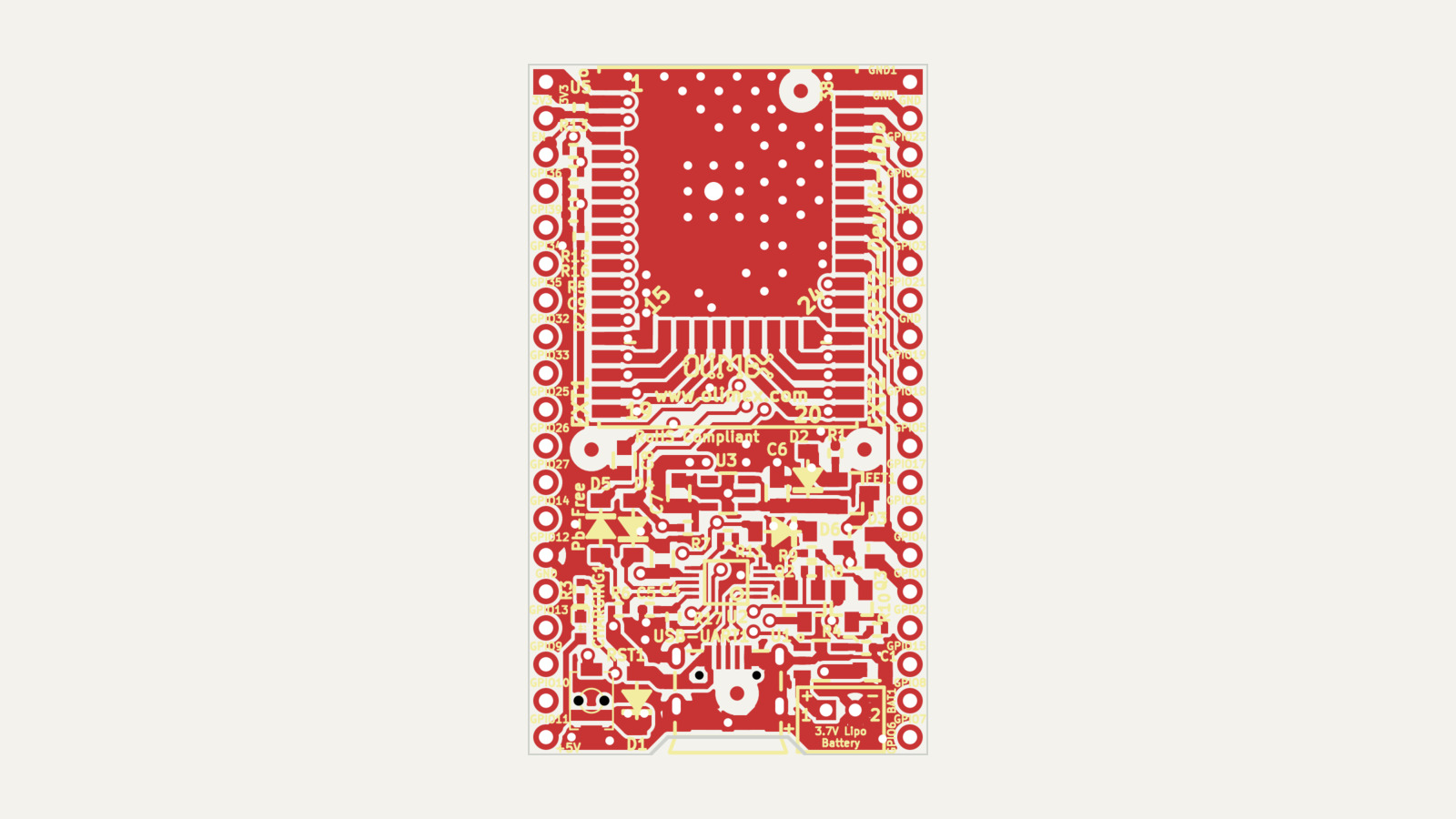
| OLIMEX ESP32-DevKit-LiPo Rev D, KiCad (Apache-2.0 hardware license) | 24 | 22 | 10 | Twin created; MCU mapped, but the board was not run |
| Raiden S0-1 ESP32-S3 board, KiCad (CERN-OHL-P-2.0 license) | 33 | 4 | 5 | Design-only; ESP32-S3 model is missing |
“Mapped” means the importer connected the reference part to a LabWired catalog model. “Unmodeled” means the file contained a part with no model in this run. “Ignored” means a part with no simulation behavior, such as a mechanical item. A twin-ready result still may have gaps. The OLIMEX import left 22 parts unmodeled and 9 ESP32 pins unwired.
These reference imports were coverage checks, not firmware runs or physical-board tests. The two Altium boards correctly stayed design-only because neither had a mapped MCU. The newer ESP32-S3 KiCad board also stayed design-only because its processor model is not in the catalog. That is the useful boundary: the tool can accept a board file and still tell you exactly why it cannot yet run the whole design.
How to read the coverage report
Start with the unmodeled list and the MCU mapping. A mapped component identifies a candidate simulator model; it does not prove that every connection on the original board has a supported behavior. Inspect pin mappings and unwired pins before applying a twin. A design-only import is useful for reviewing the source and planning model work, but it is not a firmware test.
The OLIMEX result illustrates the distinction. LabWired created a twin, yet 22 parts were unmodeled and nine ESP32 pins were unwired. We did not run firmware on that imported design. The 24 mapped parts should not be read as a claim that the complete board was simulated.
To repeat the coverage check, import a linked public reference file with the LabWired PCB plugin. Inspect the returned component and pin coverage. Compare the report with the source design before asking to run anything. Coverage can change as the catalog and importer change; the table records the results of this run.
ChatGPT creates the mixed-signal example
For the runnable proof, ChatGPT placed four parts in LabWired: an Arduino Uno, a TMP36 temperature sensor, a 220 Ω resistor, and a red LED. The TMP36 output is wired to analog input A0. Digital pin D9 drives the LED through the resistor.
The wiring used for the demo is:
| Connection | Purpose |
|---|---|
| Uno 5V → TMP36 VCC | Sensor supply |
| TMP36 VOUT → Uno A0 | Analog sensor input |
| TMP36 GND → Uno GND | Common return |
| Uno D9 → 220 Ω resistor → LED anode | Digital alarm output |
| LED cathode → Uno GND | LED return |
The two ground connections share a net. The complete design therefore has five electrical nets, even though the diagram contains six wire segments.
Reproduce the workflow
- Connect the LabWired PCB plugin to ChatGPT. Ask it to create an Arduino Uno temperature alarm using a TMP36, a 220 Ω resistor, and a red LED. Specify the connections in the table above.
- Ask it to write firmware that reads A0, reports temperature over serial, and drives D9 high at or above 30 °C. Inspect the diagram and code before running.
- Ask the plugin to run a two-state verification. Start the simulated sensor at 20 °C and change it to 35 °C after 1,000,000 simulated cycles. Inspect the serial result and D9 transition.
- Ask the plugin to create and route the PCB, then inspect the unrouted-net count and design-rule report. Compare the routed board with the source diagram.
- Open the saved demo and press Run to inspect the circuit and its saved firmware in the browser. The saved share is a way to open the circuit; repeat the two-state stimulus through the verification workflow to reproduce the specific observations below.
For example, the initial request can be:
Create a simulated Arduino Uno temperature alarm. Connect a TMP36 to 5V,
GND and A0. Connect D9 through a 220 ohm resistor to a red LED and return
the LED to GND. Write firmware that prints temperature and turns the LED on
at 30 C. Verify 20 C followed by 35 C, then route and inspect the PCB.
Review the plugin’s tool results at each step. A generated circuit is a starting point; the reported run, routing, and model coverage are separate evidence.
flowchart LR
  A["TMP36 model<br/>20 °C → 35 °C"] -- "analog output" --> B["Uno A0<br/>analogRead()"]
  B --> C["threshold ≥ 30 °C"]
  C -- "digital HIGH" --> D["D9 → 220 Ω → LED"]
The simulated sensor input crosses the firmware threshold. The firmware drives the digital LED output.
The firmware reads the sensor through the ADC, converts the result to Celsius, and raises the alarm output at 30 °C:
const int SENSOR = A0;
const int ALARM_LED = 9;

void setup() {
  pinMode(ALARM_LED, OUTPUT);
  Serial.begin(115200);
}

void loop() {
  const int raw = analogRead(SENSOR);
  const float volts = raw * (5.0f / 1023.0f);
  const float tempC = (volts - 0.5f) * 100.0f;
  const bool alarm = tempC >= 30.0f;
  digitalWrite(ALARM_LED, alarm ? HIGH : LOW);
  Serial.print("TEMP_C=");
  Serial.print(tempC, 1);
  Serial.println(alarm ? " ALARM" : " CLEAR");
  delay(100);
}
The calculation assumes a 10-bit ADC and a 5 V reference. It scales the ADC reading to volts, subtracts the sensor’s 0.5 V offset, and applies 100 °C per volt. One ADC count represents about 4.89 mV, or 0.49 °C in this calculation. That quantization helps explain why a simulated 20 °C input prints as 19.9 °C.
We verified two simulated TMP36 inputs: 20 °C at startup, then 35 °C after 1,000,000 simulated cycles. The serial output included:
TEMP_C=19.9 CLEAR
TEMP_C=35.0 ALARM
The verification result was model_verified: both expected serial states appeared and D9 changed once as the threshold was crossed. This demonstrates the analog sensor model feeding the firmware’s ADC calculation and the digital alarm response. It is a simulator result, not a measurement on an Arduino board.
| Simulated input | Observed serial output | Expected alarm state |
|---|---|---|
| 20 °C at startup | TEMP_C=19.9 CLEAR | D9 low |
| 35 °C after 1,000,000 cycles | TEMP_C=35.0 ALARM | D9 high |
The verification reported one D9 change. The output is useful for checking the firmware’s decision at these two inputs. It does not establish sensor accuracy, noise behavior, analog waveform shape, or the physical LED current.
Route and inspect the board
The PCB plugin generated a two-layer board, routed all five nets, and reported zero unrouted nets and zero DRC violations. Comparing the firmware run against the source diagram and routed copper returned equivalent; both run oracles passed.
These results answer different questions. Routing says the generated layout connects the five nets with no unrouted links in this run. The DRC report says that the checks performed found no violations. The equivalence result compares the simulated behavior against the source diagram and routed copper. None of those results alone verifies a real module’s pin order, analog signal integrity, manufacturing readiness, or a physical assembly.
This is a workflow example, not a finished module design. The generated Uno module footprint uses a canonical pin order. Verify that order against the physical module before committing copper. The simulator used an ideal 5 V VDD rail. It did not simulate power-on or brown-out reset behavior.
The TMP36 response is tested through its simulated temperature input and the firmware’s ADC-derived serial values. The scope instrument path did not produce analog samples for this board, so this article does not present a voltage waveform or meter reading. The digital D9 transition and the PCB routing report are separate, explicit observations.
No physical board was fabricated or tested. This article uses a synthetic circuit and openly licensed reference files only. Do not use the public demo link for customer-owned designs or derived details; those belong in the customer’s approved private environment.