Blink, a button, and Wi-Fi on the ESP32-S3, with a lab for each step
Category: Tutorial
This is the first hour on an ESP32-S3-DevKitC-1 N16R8. This hour has three programs. The first program writes GPIO4. The second program reads GPIO5. The third program calls WiFi.begin. The third program sends GET /status. Each program has the connections. Each program has the sketch. Each program has a LabWired lab on this page. Press Run. The chip in the iframe is a model of this S3. You flash this Arduino sketch.
The longer lesson is Getting started with the ESP32. The lesson includes the Arduino IDE settings. The lesson includes the upload failures.
The board
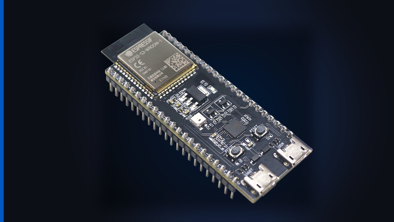
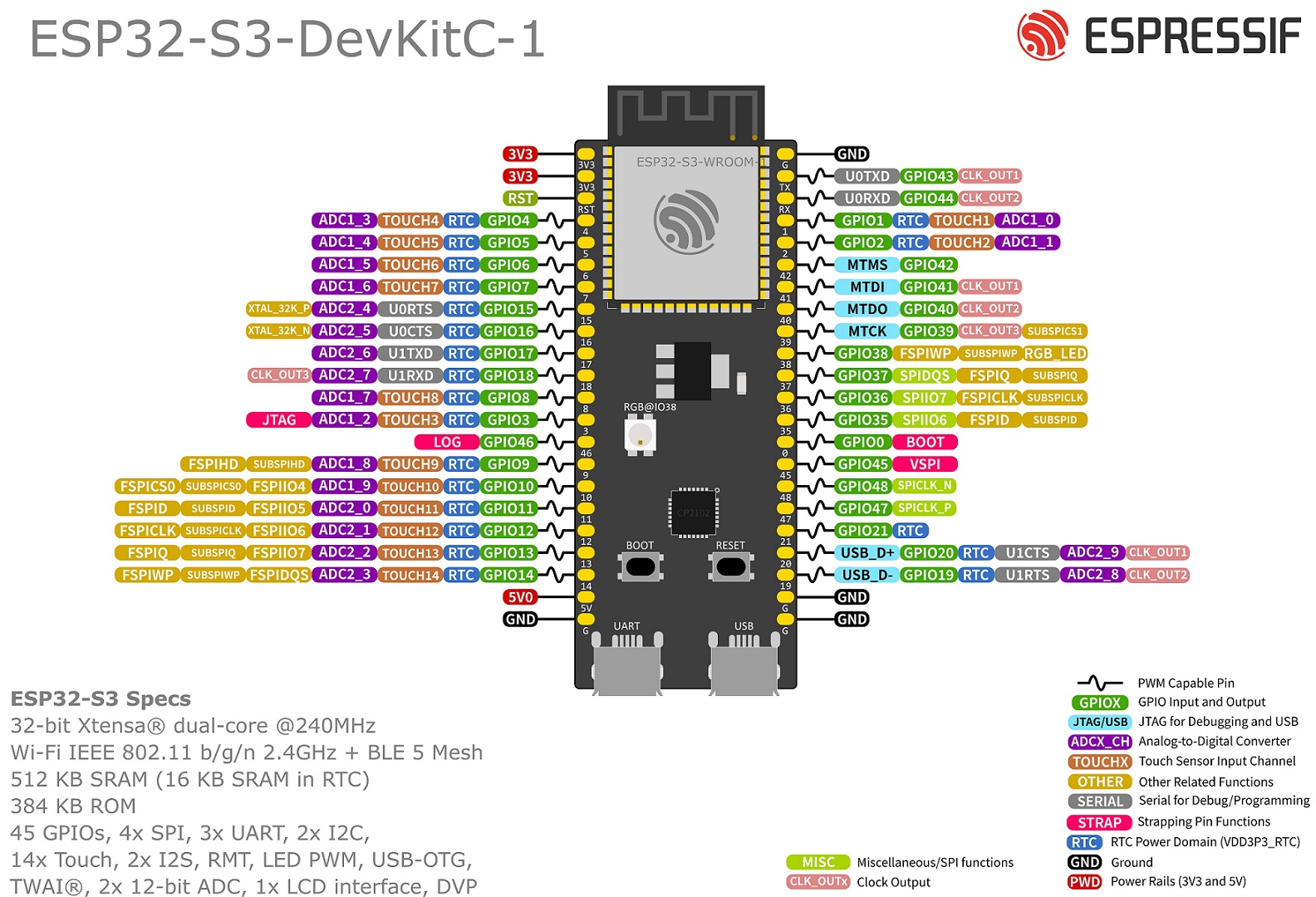
The metal shield reads ESP32-S3-WROOM-1-N16R8 or ESP32-S3-N16R8. GPIO4 is the first GPIO on the left header. GPIO4 is under the two 3V3 pins. GPIO4 is under RST. GPIO5 is the next pin down from GPIO4.
This board is not a SuperMini. This board is not an S3-Zero. Those boards have different headers.
Blink GPIO4
Connections
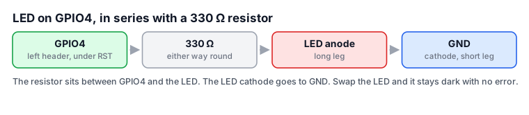
| Board pin | Goes to | Notes |
|---|---|---|
| GPIO4 | 330 ohm resistor, one end | Left header, first GPIO under RST |
| resistor (other end) | LED anode | Long leg. The resistor is in series. |
| GND | LED cathode | Short leg, flat edge of the plastic |
Code
LED_PIN is 4. That pin is the net above.
#include <Arduino.h>

const int LED_PIN = 4;
uint32_t count = 0;

void setup() {
  Serial.begin(115200);
  pinMode(LED_PIN, OUTPUT);
  Serial.println("ESP32-S3 up. First blink.");
}

void loop() {
  digitalWrite(LED_PIN, HIGH);
  Serial.print("blink ");
  Serial.println(++count);
  delay(500);
  digitalWrite(LED_PIN, LOW);
  delay(500);
}
Lab. Press Run. The LED follows GPIO4. Serial prints blink and a count. Change delay(500). Run the sketch again.
On silicon, the sketch is the same. In the Arduino IDE, select ESP32S3 Dev Module. Set the flash to 16MB. Select OPI PSRAM. Enable USB CDC on boot. The lesson has the full list.
Read GPIO5
Keep the LED. Add the button.
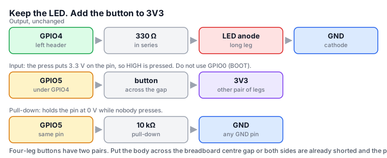
Connections
| Board pin | Goes to | Notes |
|---|---|---|
| GPIO4 | 330 ohm, then LED anode, then GND | Same as the blink |
| GPIO5 | one pair of button legs | Left header, under GPIO4. Do not use GPIO0 (BOOT). |
| GND | the other pair of button legs | With INPUT_PULLUP, do not add an extra resistor. |
Code
INPUT_PULLUP holds GPIO5 high. A press to GND reads LOW.
#include <Arduino.h>

const int LED_PIN = 4;
const int BUTTON_PIN = 5;

void setup() {
  Serial.begin(115200);
  pinMode(LED_PIN, OUTPUT);
  pinMode(BUTTON_PIN, INPUT_PULLUP);
  Serial.println("ESP32-S3 up. Button on GPIO5.");
}

void loop() {
  bool pressed = digitalRead(BUTTON_PIN) == LOW;
  digitalWrite(LED_PIN, pressed ? HIGH : LOW);
  Serial.println(pressed ? "pressed" : "open");
  delay(50);
}
Lab. Click the button on the canvas. The LED follows GPIO5. Serial prints pressed or open.
Join Wi-Fi and GET /status
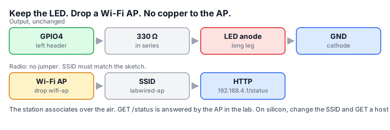
Keep the LED on GPIO4. Drop a Wi-Fi AP on the canvas. The AP has no pins. The S3 associates over the air. The sketch still uses WiFi.begin. The sketch still uses WiFiClient.
The SSID in the lab is labwired-ap. The AP answers GET /status at 192.168.4.1. On silicon, change the SSID to your 2.4 GHz network. Add a password. On silicon, GET a host on that network.
Connections
| Board pin | Goes to | Notes |
|---|---|---|
| GPIO4 | 330 ohm, then LED anode, then GND | Same as the blink |
| (none) | Wi-Fi AP | Drop wifi-ap on the canvas. The SSID is labwired-ap. Do not use a jumper. |
Code
#include <Arduino.h>
#include <WiFi.h>

const int LED_PIN = 4;

void setup() {
  Serial.begin(115200);
  delay(2000);
  pinMode(LED_PIN, OUTPUT);
  Serial.println("joining labwired-ap");
  WiFi.begin("labwired-ap");
  while (WiFi.status() != WL_CONNECTED) {
    delay(400);
    Serial.print(".");
  }
  Serial.println();
  Serial.println("joined");

  WiFiClient c;
  if (!c.connect(IPAddress(192, 168, 4, 1), 80)) {
    Serial.println("GET failed");
    return;
  }
  c.print("GET /status HTTP/1.1\r\nHost: 192.168.4.1\r\nConnection: close\r\n\r\n");
  unsigned long dl = millis() + 5000;
  while (millis() < dl && (c.connected() || c.available())) {
    while (c.available()) {
      Serial.write(c.read());
    }
    delay(10);
  }
  c.stop();
  digitalWrite(LED_PIN, HIGH);
}

void loop() {
  delay(1000);
}
Lab. Press Run. Serial prints joining labwired-ap. Serial then prints joined. Serial then prints the HTTP response from the AP. The LED goes high after the GET.
Dots continue forever in the lab if the SSID in the sketch is not labwired-ap. Dots continue forever in the lab if the AP part is missing. Dots continue forever on silicon if the name is wrong. Dots continue forever on silicon if the password is wrong. Dots continue forever on silicon if the network is 5 GHz only.
What to do next
Flash the same three sketches. The getting-started lesson has the Arduino IDE settings. The lesson has the upload failures. These failures stop the first upload.
Open the Playground to wire the next circuit. The MCP server runs the same chip model from an agent.