Getting started with the ESP32
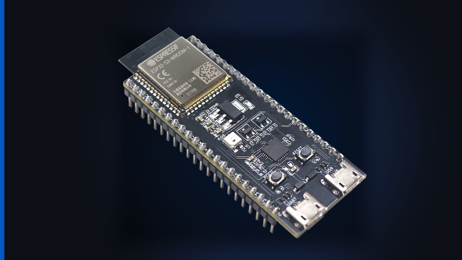
This lesson uses the ESP32-S3-DevKitC-1 N16R8 in LabWired. Pick that board in the Playground.
The first two programs have a lab. The lab is a model of the S3. The model runs the Arduino sketch in the editor. Change a pin or a delay. Press Run. A virtual board then runs your code. The third program is Wi-Fi. Wi-Fi needs a real board. The twin does not model the S3 radio yet. This lesson states that limit. This lesson does not show a lab that cannot join.
What you need: a browser. You drop the board, the LED, the resistor, and the button on a canvas. If you own the real board, use Tools > Deploy. The same sketches flash to that board.
Contents
The board
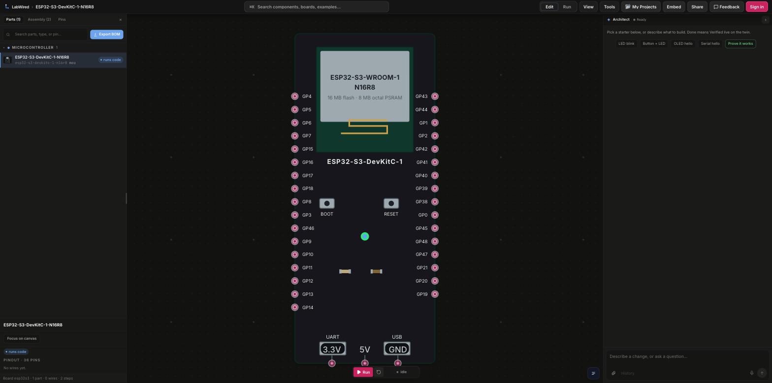
Pick the N16R8 DevKitC-1 on the canvas. Drop an LED and a 330 ohm resistor on the canvas. Later, drop a button and a Wi-Fi AP on the canvas.
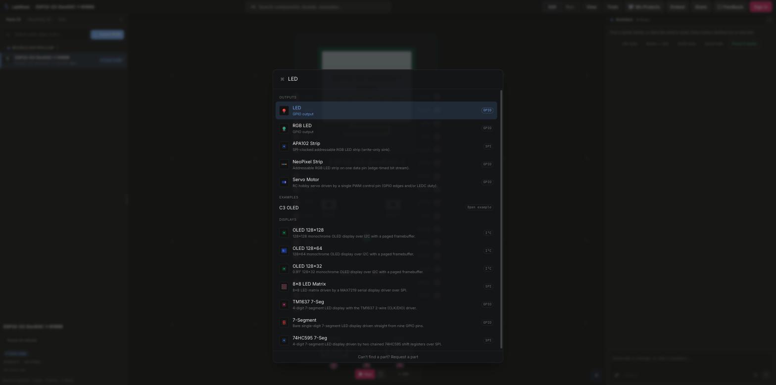
Press ⌘K to add a part.
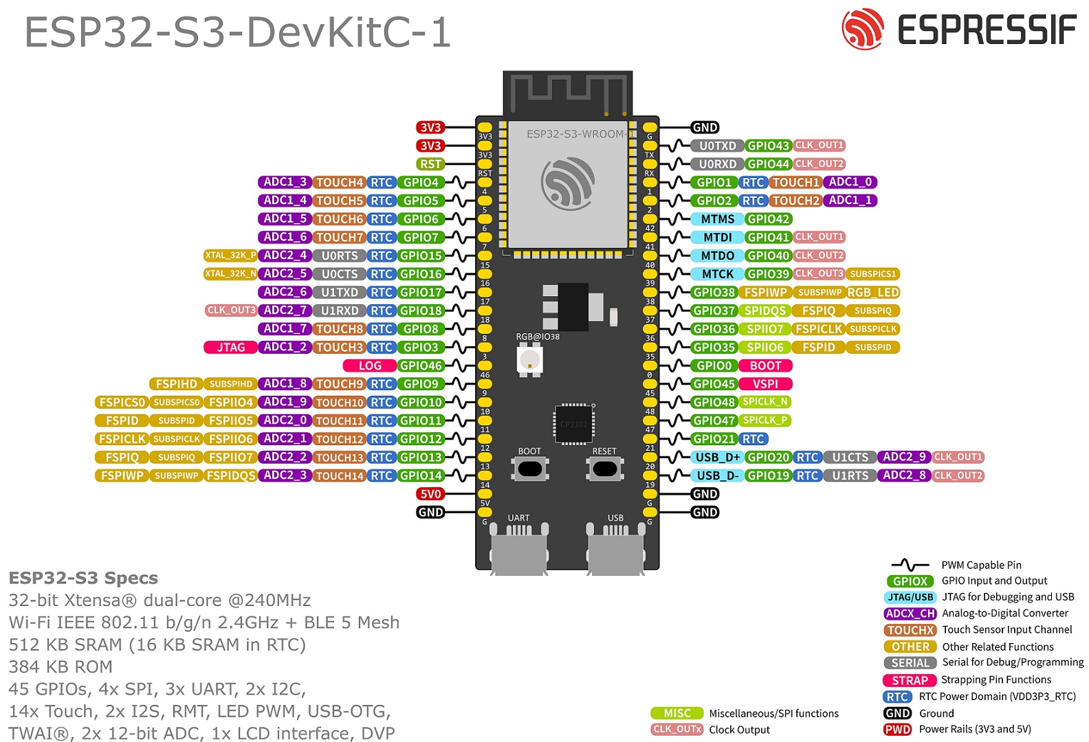
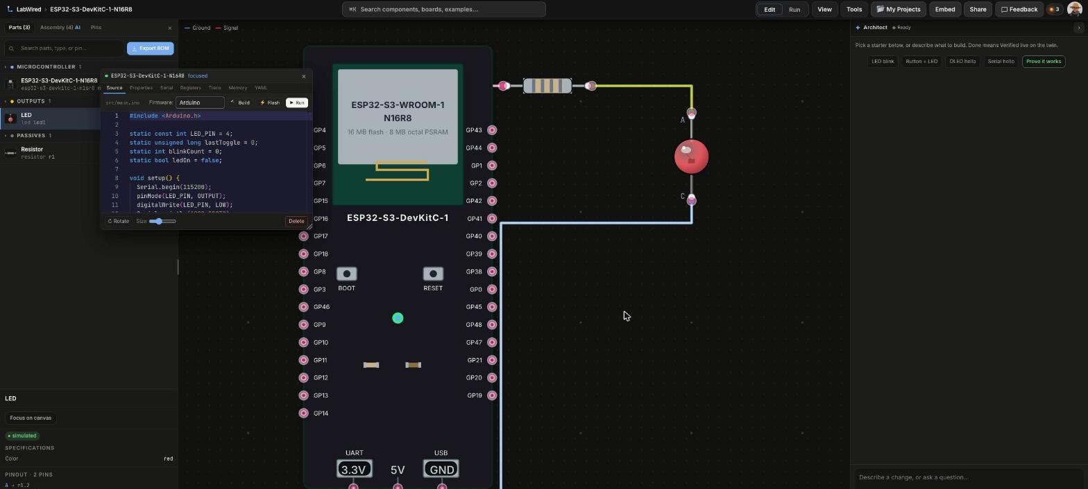
Keep this pin layout open while you wire. GPIO4 is the first GPIO on the left header, under the two 3V3 pins and RST. GPIO5 is the next pin down.
Blink GPIO4
Connections
| Board pin | Goes to | Notes |
|---|---|---|
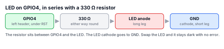
| GPIO4 | 330 ohm resistor, one end | Left header, first GPIO under RST |
| resistor (other end) | LED anode | Long leg. Resistor in series |
| GND | LED cathode | Short leg, flat edge of the plastic |
Code
Run this LED blink code in the browser. The code uses Arduino.
LED_PIN is 4. setup() runs once after reset. loop() defines the code that repeats.
#include <Arduino.h>

const int LED_PIN = 4;
uint32_t count = 0;

void setup() {
  Serial.begin(115200);
  pinMode(LED_PIN, OUTPUT);
  Serial.println("ESP32-S3 up. First blink.");
}

void loop() {
  digitalWrite(LED_PIN, HIGH);
  Serial.print("blink ");
  Serial.println(++count);
  delay(500);
  digitalWrite(LED_PIN, LOW);
  delay(500);
}
How it works
const int LED_PIN = 4;names the pin once. The value is 4 because that net is in the table above. Change this line and the wire. If you do not change them, nothing lights.pinMode(LED_PIN, OUTPUT)sets GPIO4 to push-pull output mode. Without this call, the pin stays an input. The LED never gets a drive.digitalWrite(LED_PIN, HIGH)and thenLOWmake the blink.loop()starts again when it returns.delay(500)sets the time that you see. The LED is on for 500 ms. The LED is off for 500 ms. Halve the delay. The LED then blinks twice as fast.Serial.begin(115200)opens the console. In the lab, the console is the serial pane. On a real board, the console is the Serial Monitor at the same speed.
Run it. Use this wiring and this sketch. Press Run. The LED blinks on GPIO4. Serial prints blink and a count. Change delay(500). Run the sketch again. The blink time is then different.
If nothing blinks
- The LED is in backwards. The LED conducts in one direction only. Connect the long leg to the resistor. Connect the short leg to GND.
- The wire is on the wrong pin. The table says GPIO4. The canvas labels that pin GP4.
- The serial pane shows a count. The LED stays dark. The code runs. The fault is in the three connections.
Tools > Deploy puts the same sketch on a real board.
Read GPIO5
Keep the LED on GPIO4. Add the button.
Connections
| Board pin | Goes to | Notes |
|---|---|---|
| GPIO4 | 330 ohm, then LED anode, then GND | Same as the blink |
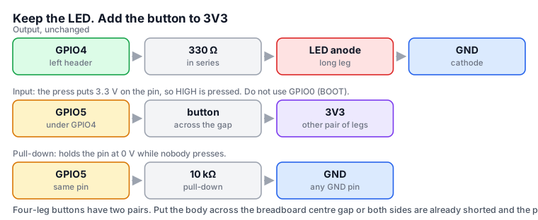
| GPIO5 | one pair of button legs | Left header, under GPIO4 |
| 3V3 | the other pair of button legs | A press puts 3.3 V on the pin |
| GPIO5 | 10 k ohm, other end to GND | Pull-down. It holds the pin at 0 V when no person presses the button |
Code
BUTTON_PIN is 5. The 10 k resistor holds GPIO5 at 0 V. A press connects GPIO5 to 3.3 V. A press then reads HIGH.
#include <Arduino.h>

const int LED_PIN = 4;
const int BUTTON_PIN = 5;

void setup() {
  Serial.begin(115200);
  pinMode(LED_PIN, OUTPUT);
  pinMode(BUTTON_PIN, INPUT);
  Serial.println("ESP32-S3 up. Button on GPIO5.");
}

void loop() {
  bool pressed = digitalRead(BUTTON_PIN) == HIGH;
  digitalWrite(LED_PIN, pressed ? HIGH : LOW);
  Serial.println(pressed ? "pressed" : "open");
  delay(50);
}
How it works
- An input pin with no drive signal is floating. The pin reads charge near the pin. That read is noise. The 10 k resistor to GND is the correction. The resistor holds GPIO5 at 0 V. The resistor holds the pin weakly. The button can still change the pin level.
- You press the button. The button then connects GPIO5 directly to 3.3 V. The button connection overrides the resistor. The pin reads HIGH. For this reason, the code compares the pin value with
HIGH. digitalWrite(LED_PIN, pressed ? HIGH : LOW)sets the LED from the input state. You can then see the button state. You do not need to read the console.delay(50)is a crude debounce. A mechanical button chatters for a few milliseconds. The delay waits. The code then reads the pin again.- The ESP32 also has an internal pull-up resistor on every pin.
pinMode(BUTTON_PIN, INPUT_PULLUP)does the same task. Connect the button to GND instead of 3V3. You then need no resistor of your own. The logic inverts. A press reads LOW. Use this method on a real board. The twin does not model the internal pull-up yet. The lab below uses the resistor that you can see.
Run it. Click the button on the canvas. Then tick Pressed in the panel that opens. The LED shows the GPIO5 level. Serial prints pressed or open.
If the pin always reads pressed. GPIO5 stays at 3.3 V. No part pulls the pin down. The 10 k resistor can be absent. Or the four-leg button can be in the wrong rotation. Its legs are two pairs. Each pair is already joined inside the button. The wrong rotation shorts 3V3 to the pin. The short is permanent. Sit the body across the centre gap.
Wi-Fi and HTTP
Keep the LED on GPIO4. The board joins an access point. The board requests a page from that access point over HTTP. The LED lights when the answer arrives. All of this section runs on real hardware. The in-page twin does not simulate the S3 radio yet. Read this section with a real board connected.
Connections
| Board pin | Goes to | Notes |
|---|---|---|
| GPIO4 | 330 ohm, then LED anode, then GND | Same as the blink |
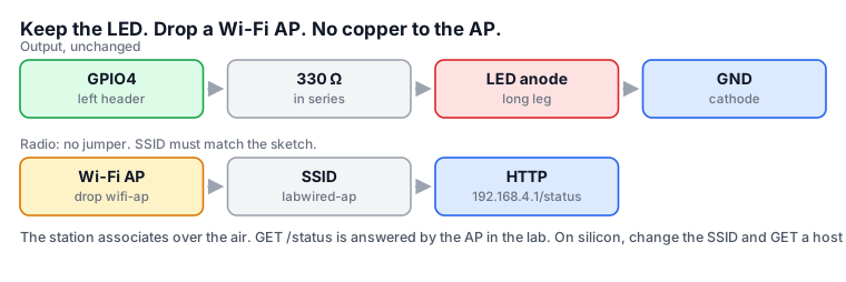
| (antenna) | your access point | No jumper. The join is WiFi.begin(ssid, password) in the sketch. |
/status over HTTP.Code
The SSID in WiFi.begin("labwired-ap") must match the access point SSID. WiFiClient connects to the access point. On your board, change the SSID to your 2.4 GHz network. Add a password for that network.
#include <Arduino.h>
#include <WiFi.h>

const int LED_PIN = 4;

void setup() {
  Serial.begin(115200);
  delay(2000);
  pinMode(LED_PIN, OUTPUT);
  Serial.println("joining labwired-ap");
  WiFi.begin("labwired-ap");
  while (WiFi.status() != WL_CONNECTED) {
    delay(400);
    Serial.print(".");
  }
  Serial.println();
  Serial.println("joined");

  WiFiClient c;
  if (!c.connect(IPAddress(192, 168, 4, 1), 80)) {
    Serial.println("GET failed");
    return;
  }
  c.print("GET /status HTTP/1.1\r\nHost: 192.168.4.1\r\nConnection: close\r\n\r\n");
  unsigned long dl = millis() + 5000;
  while (millis() < dl && (c.connected() || c.available())) {
    while (c.available()) {
      Serial.write(c.read());
    }
    delay(10);
  }
  c.stop();
  digitalWrite(LED_PIN, HIGH);
}

void loop() {
  delay(1000);
}
How it works
WiFi.begin("labwired-ap")starts the join. The string must match the access point SSID exactly. A string that does not match is the most common failure.- The
while (WiFi.status() != WL_CONNECTED)loop prints a dot every 400 ms. Association takes time. The dots separate an attempt that continues from a stuck join. WiFiClientuses plain TCP.c.connect(IPAddress(192,168,4,1), 80)opens the socket. Thec.print("GET /status HTTP/1.1...")line is the full HTTP request. The sketch writes that request directly.- The read loop reads all available bytes until
millis() + 5000. A silent server cannot hold the sketch in that loop. - The LED goes high only after the GET returns. You can then see success with no console.
Run this step on the board. Do not run this step in the page. This is the one step in this lesson that has no lab. LabWired does not model the S3 radio yet. The twin cannot join anything. Put this sketch on a real board with Tools > Deploy. Change the SSID to your own 2.4 GHz network. Add the password as a second argument to WiFi.begin. Point the connect call at a host on that network. Serial then prints joined. Serial then prints the response. The LED goes high after the GET.
If the sketch prints dots and does not stop. The name or the password is wrong. Or the network is 5 GHz only. The ESP32 joins 2.4 GHz.
Open the Playground to wire the next circuit.
A different ESP32
Pin numbers are not the same on every board in the family. A SuperMini and an S3-Zero have different headers.
| Chip | Core | Radio | USB |
|---|---|---|---|
| ESP32 | Two Xtensa LX6 | Wi-Fi 4, Bluetooth Classic and LE | Converter chip only |
| ESP32-S3 | Two Xtensa LX7 | Wi-Fi 4, Bluetooth LE | In the chip. This DevKitC-1 also has a converter port |
| ESP32-C3 | One RISC-V | Wi-Fi 4, Bluetooth LE | In the chip |
| ESP32-C6 | One RISC-V | Wi-Fi 6, Bluetooth LE, 802.15.4 | In the chip |
| ESP32-H2 | One RISC-V | Bluetooth LE, 802.15.4. No Wi-Fi | In the chip |
The H2 has no Wi-Fi. The H2 cannot run this join-and-GET sketch.
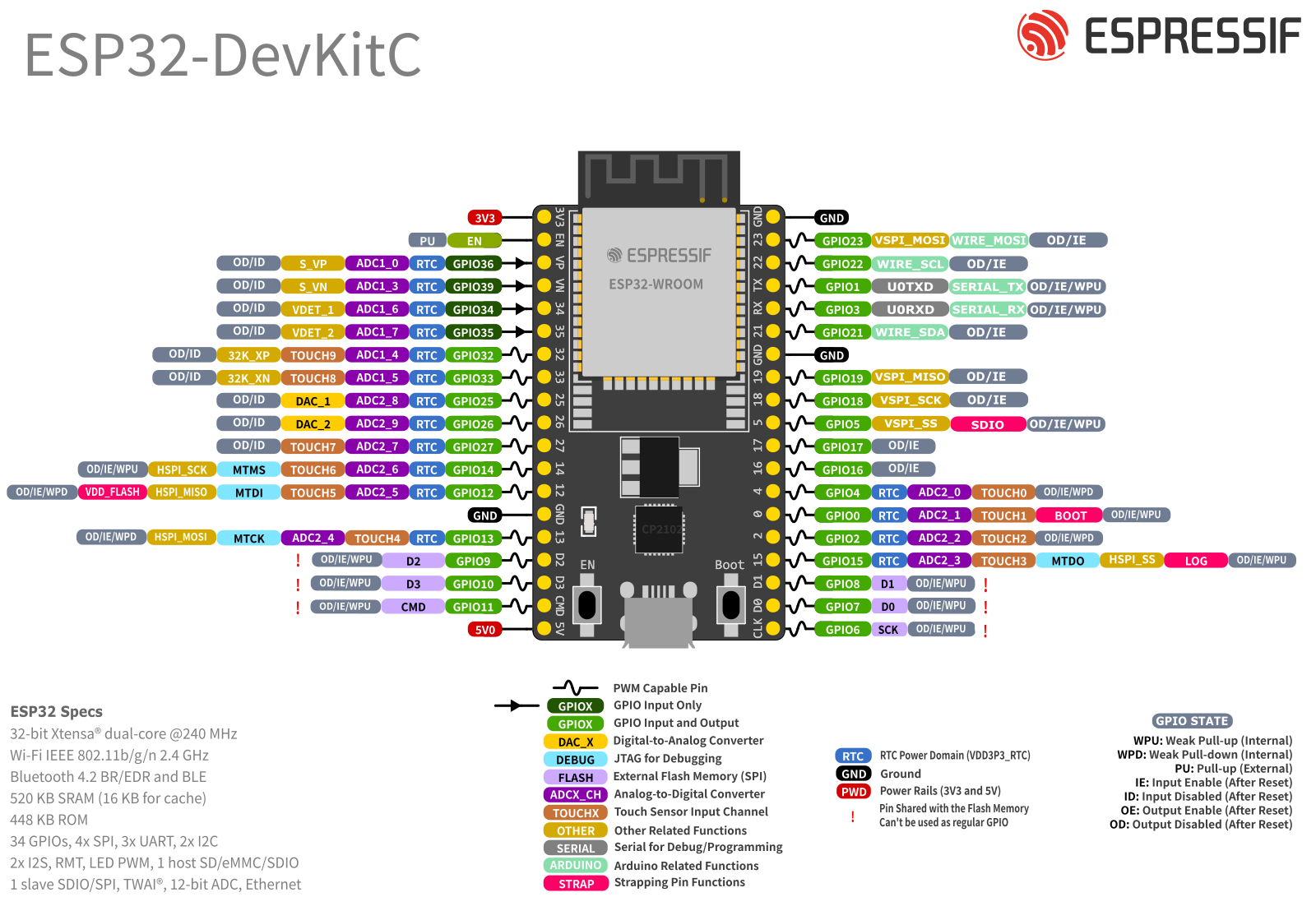
Most older tutorials use the classic DevKitC V4:
If a failure took you a day to find, post it on r/labwired. Or send a message to contact@labwired.com.