Two boards, one wire: GPIO nets between MCUs
Category: Engineering
A lot of products have two microcontrollers. They usually talk over a UART. Next to it there are a few plain wires: an interrupt line, a ready line, sometimes one alert line that every board can pull low. LabWired could already run several chips and connect their UARTs. It could not connect a GPIO pin on one chip to a GPIO pin on another. Now it can.
The setup
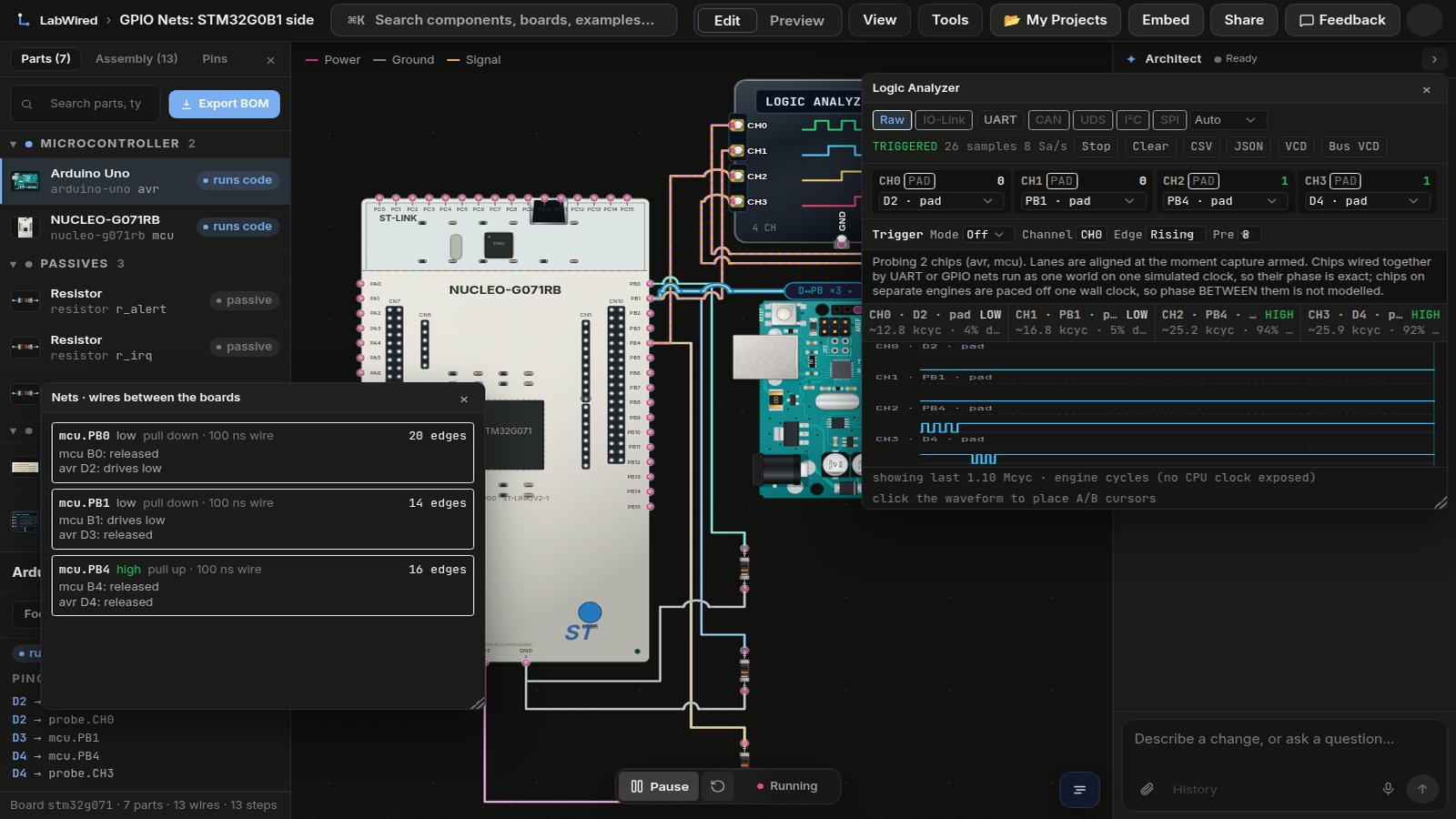
I used two different chips: an STM32G0B1 (on a NUCLEO-G071RB board in the drawing) and an Arduino Uno. Each runs its own firmware. Three wires connect them:
| Wire | Direction | Pull | What the firmware does |
|---|---|---|---|
| irq | Uno → STM32 | down | The Uno pulses it 10 times. The STM32 counts rising and falling edges with an EXTI interrupt. |
| ready | STM32 → Uno | down | The STM32 pulses it 7 times. The Uno counts by polling the pin. |
| alert | both | up | Shared open-drain line. The STM32 pulls it low 5 times, then the Uno 3 times, and each counts the other’s pulses. |
Both boards print their counters on their own UART.
How a net works
A gpio_net connects pins of two or more machines into one net. On every edge it works out the level like this: if any pin drives low, the net is low. If none drives low and one drives high, it is high. If nothing drives it, the pull resistor decides. With no driver and no pull it reads 0 and is reported as floating. That covers open-drain too: pins that only pull low or release, plus a pull-up, give you a wired-AND.
An edge reaches the other chips 100 ns later by default, on a defined CPU cycle of each of them. It goes in through the same input path as a button press, so EXTI interrupts and timer captures see it as a normal edge.
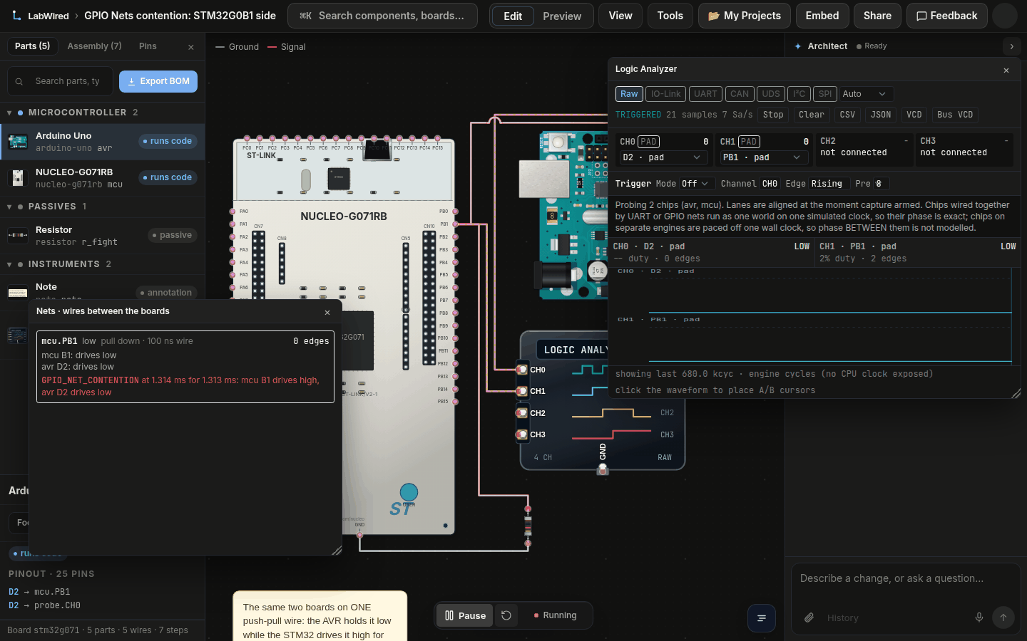
If one pin drives 0 and another drives 1 at the same time, the run reports GPIO_NET_CONTENTION. The report has the start and end time and what each pin was driving. The net then reads low.
Results don’t depend on which machine is stepped first or on the simulation round length. The test runs the example in both node orders and with rounds from 10 ns to 100 ns. It compares every counter, every UART line and every delivered edge.
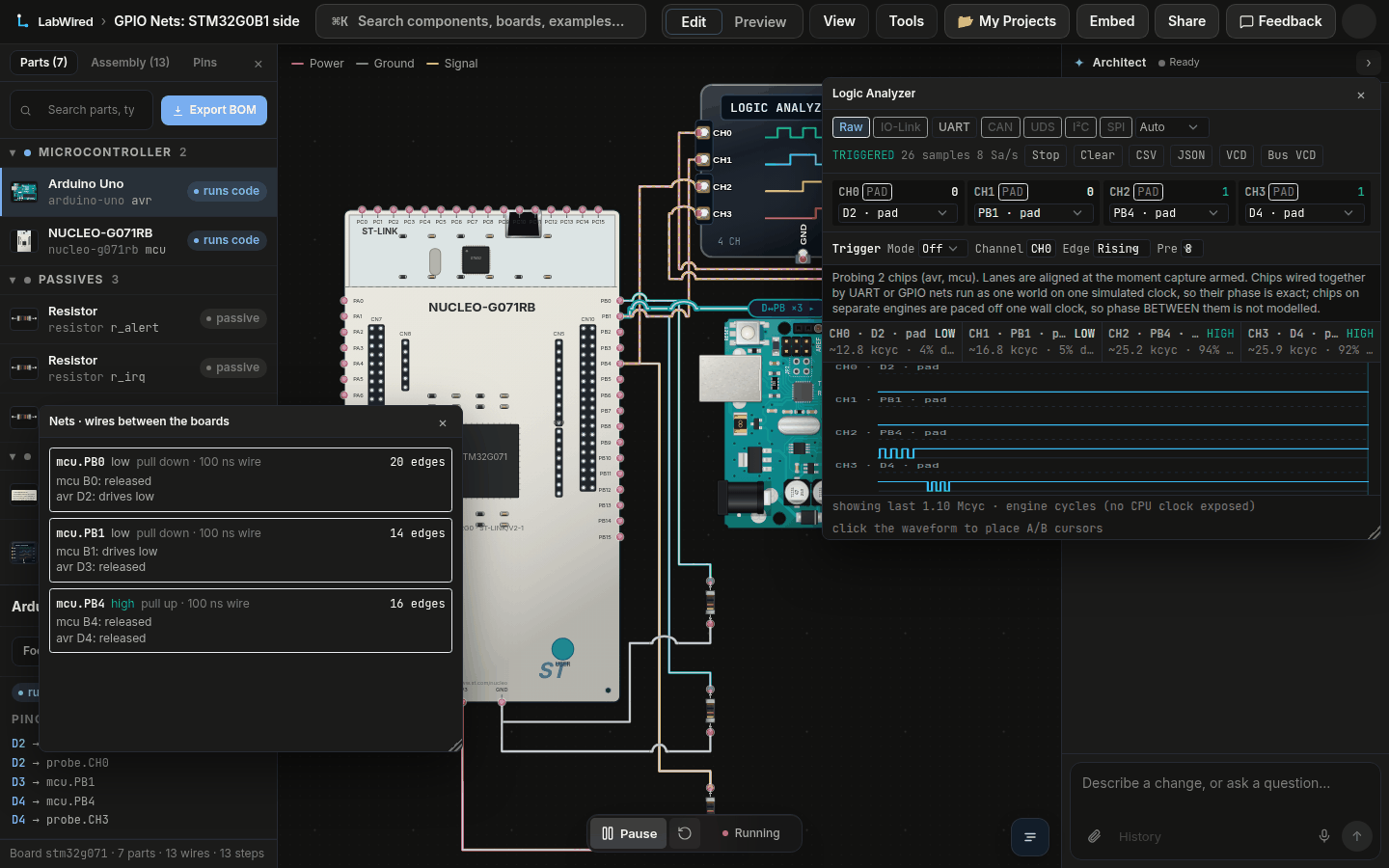
In the playground both boards run in one simulation, the same way the hosted runner does it. The Nets window lists each wire with its level, its edge count and which pin drives it.
Try it
Open the two-boards lab and press Run. In the playground build every delay in the firmware is 20 times longer, so the pulses last hundreds of microseconds. You can see them in the logic analyzer. The counts are the same as in the fast build.
The numbers
Serial output from the two boards:
STM irq r=10 f=10 alert r=3 f=3
AVR ready=7 alert f=5 r=5
The STM32 saw 10 rising and 10 falling edges on irq and 3 and 3 on alert. The Uno saw 7 ready pulses and 5 falling and 5 rising edges on alert. The nets count the same from the wire side: irq 20 edges, ready 14, alert 16. A pulse is two edges, and alert carries 5 + 3 pulses.
From the command line:
labwired test --script examples/gpio-net-two-boards/test.yaml --output-dir out
out/result.json has a gpio_nets block with each net’s level, edge count and diagnostics. CI checks these counts on every change.
The second lab, Two boards, one fight, puts both boards on one push-pull wire. The Uno holds it low and the STM32 drives it high for 50 µs. The report names both pins, B1 driving high and D2 driving low, with the time the conflict started and ended.
Limits
- ESP32-family chips and the RP2040 can’t be on a net yet. On ESP32, wires between two MCUs are treated as serial.
- The F1 and F4 EXTI models don’t react to edges coming from another chip. Use a G0 or U5, or poll the pin.
- The ATmega328P model has no pin-change interrupt, so the Uno polls. While one of its pins is on a net it also doesn’t fast-forward idle time.
- Internal pull-ups of a chip are not part of the net. Put the pull resistor on the net.
- No bit-level I2C or SPI between two MCUs yet. Those use their own connections.
- Nets with 100 ns latency make a run slower than a single machine. Use a longer latency on wires that don’t need it.
- The mobile playground has no Nets window yet.